Brake Light Circuits
I have 2 different circuits I have developed and produced that will enhance the brake lights on the RV.
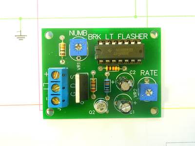
Third Brake Light Flasher
The third brake light flashing circuit that will provide a series of rapid flashes and then a steady light when the brakes are applied. Each time the brake is applied the sequence will start again.
 |
 |
This board measures 2" x 1 1/2" x 1/16" thick. I currently do not have a case available but Radio Shack has a 3 x 2 for about $3. Wiring is simple; feed the (-) with the ground to the third brake light and cut the + feed. The input goes in the (+) terminal and the remaining lead to the light goes in (LT).
Both the rate of the flashes and the number of flashes can be adjusted.
On my Sahara, I mounted a terminal block above the radiator and routed the wires through it. This will work with the existing bulb type 3rd brake light but will be more effective with a LED light.
This circuit has also been suggested for use on motorcycle brake lights as an "attention getter" to help prevent rear end collisions.
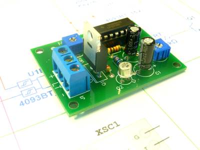
Exhaust Brake Light Blinker
Some coaches are set up so that the coach brake lights are on whenever the exhaust brake is active. I think that having the brake lights continuously lit while descending a long hill is unnecessary and possibly dangerous. A vehicle following will get accustomed to seeing the lights on and then when you do apply the coach brakes, may not realize the change until it is too late.
My circuit will change the brake light pattern when using the exhaust brake to a 5 second on, 10 second off sequence. This is obviously different from the trucks using their 4 way flashers and will appear that the driver is 'pumping' the brakes.
Any time the foot brake is applied, the lights will act normally.
 |
 |
This board measures 2" x 1 1/2" x 1/16" thick. To wire this, feed a ground to the (-) terminal and connect the feed from the exhaust brake to the (+) terminal. The (O) terminal is the output and should be routed through a diode to the brake light relay. While this circuit can handle about 5 amps, it would be wise to add a relay if one does not exist as many coaches have multiple brake lights and your trailer circuit is being fed also.
The board pictured is fitted with fixed resistors at VR1 and VR2 set for the 5, 10 timing. I can also install trimmer pots instead for anyone who wants to set their own sequence.
Click Here to download a short video of the lights with both boards installed. The 3rd brake light will institute its flash sequence any time a brake event triggers the brake light relay but the exhaust sequence only works with the exhaust brake.