Add A Soundtraxx Decoder To An Atlas U23B (1999 release)
Jim Exler, Nampa, ID June 7,2023
Steps to Remove the Shell.
1. Take off the couplers first.
2. Grab the part of the frame at the fuel tank with one hand, and grab the cab with your other hand. Watch where you put your fingers so that you don't break the handrails and other small detail parts. Squeeze gently on the shell at the ends and center to release the clips. It is a bit of a challenge.
4. Slowly pull upwards to work the shell off of the frame. Gently work both ends making sure the foot-board comes off also. Once the shell is loose from the frame, you can set it aside, there are no wires to the shell as the lights are mounted on the chassis.
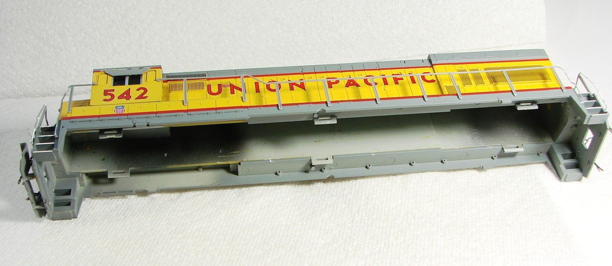 |
| This view shows the shell and you can see the 3 molded retaining clips (gray) along each side. They hook onto projections on the frame. The shell is a tight fit. Note that the lights are all mounted on the chassis so there are no wires in the shell to deal with. |
 |
Here is a picture of the model with the shell removed. This shows the motherboard with the 8 pin shorting board in place for DC operation. It also shows the original 12 volt bulbs for the lights. I will be replacing those with LEDs. The weight at the left has been marked for the cut to remove a section to accommodate the speaker. |
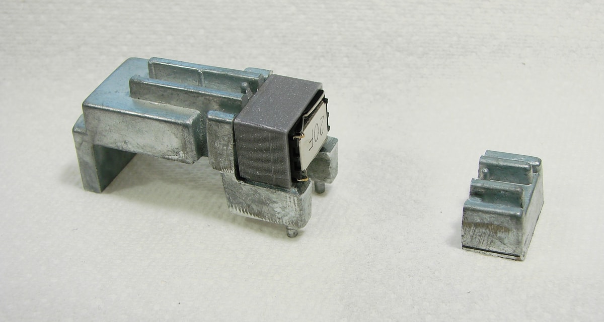 |
This is the rear weight showing the portion removed and the speaker installed. I like to use the 11 x 15 mm "cell phone" micro speakers. For this model, I used a 3D printed enclosure (11 x 15 x 10) of my own; the model file is on this site. There are also many commercial enclosures available. |
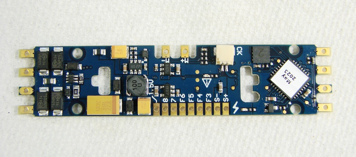 |
| Here is the Soundtraxx GE Tsunami 2 decoder 885814. It is an exact replacement for the DC board and snaps onto the original mounts. |
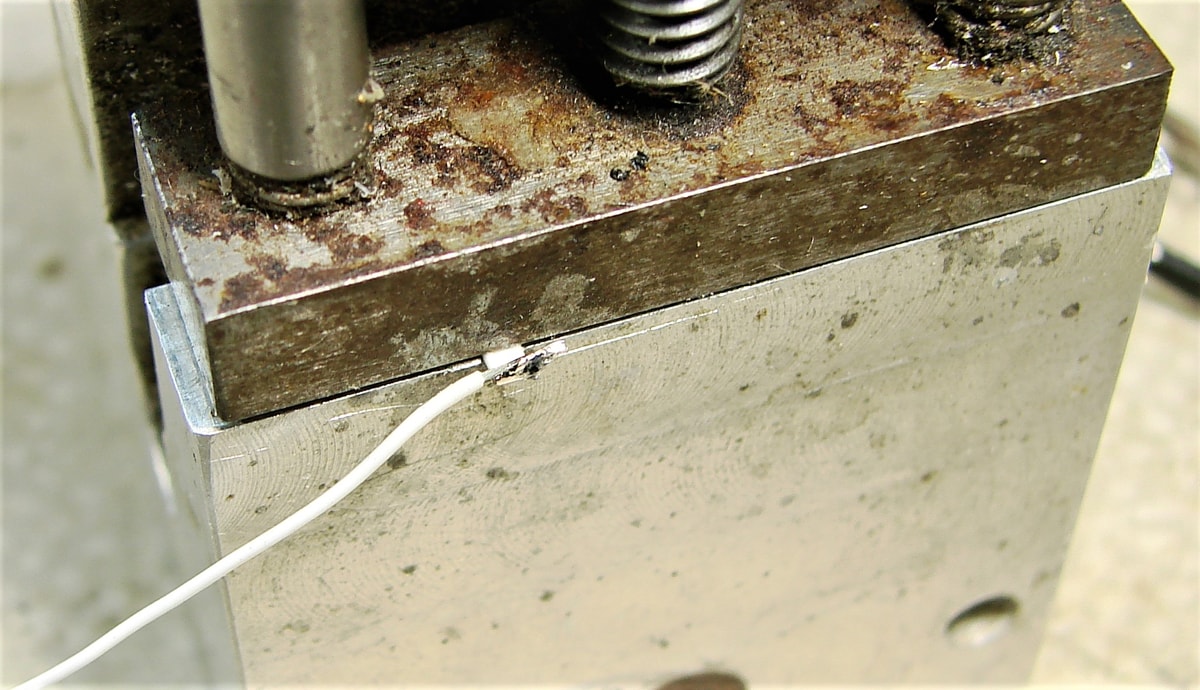 |
Now for something new to provide a 1k resistor to use LEDs for the lights. This decoder does not contain the 1k resistors so they need to be added in order to use LEDs. This method only extends the decoder terminal a slight amount beyond where it would have been with the plastic connectors and is much more compact than using standard resistors. No need to use extra insulation methods for the resistor either. I purchased some 1k (102) 1206 surface mount (smd) resistors and decided to try them here. First, I gently clamped the resistor in a bench vise. After tinning the wire, I put a small drop of liquid flux on the exposed terminal of the resistor and with the wire positioned over the terminal, I pressed a hot soldering iron with some solder on the tip to the joint. It flowed almost immediately. Now trim the excess. |
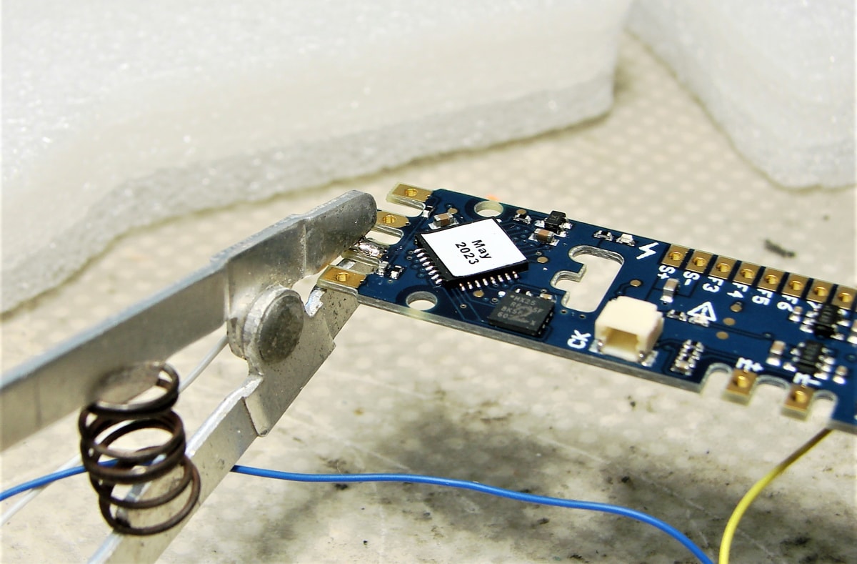 |
To attach the resistor to the decoder, I first tinned the decoder terminal being careful to make a thin even layer. I positioned the resistor over the decoder terminal with the end about even with the outer edge of the hole and, using a heat sink clamp, I held it in place. Another small drop of liquid flux at the joint and touch the soldering iron with some solder on the tip to the joint. As you can see, it worked. When the soldering was completed, I used my ohmmeter to check the resistance and insure I had not bridged the resistor. Soldering paste (solder balls mixed with paste flux) would be a viable option for this process but I didn't have any so I used what I had. |
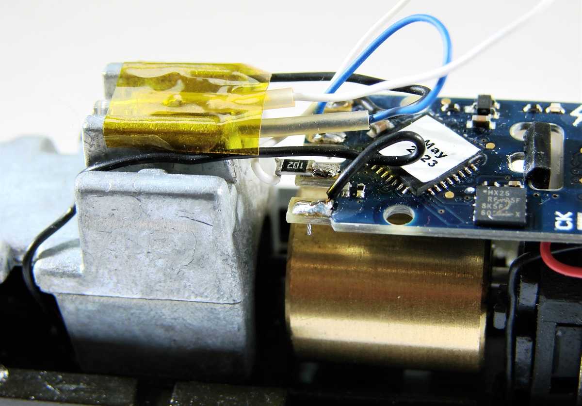 |
| This is a close up of the installed SMD resistor with the decoder mounted on the model. |
 |
 |
| Here are two views of the completed installation. |
| Now, tuck the wires out of the way and you are ready to replace the shell. Have Fun. |