Add A Soundtraxx Decoder To An Atlas MP15DC (12/2017 ver)
Jim Exler, Nampa, ID September 3, 2020
Steps to Remove the Shell. (Atlas)
1. Take off the couplers first.
2. Remove the plastic fuel tank from the frame by pulling down on the fuel tank.
3. Grab the part of the frame from which you removed the fuel tank with one hand, and grab the cab with your other hand. Watch where you put your fingers so that you don't break the handrails and other small detail parts
4. Slowly pull upwards to work the rear part of the shell off of the frame. Then work on the front part of the shell. You will have to work a little harder on the front part of the shell. Make sure that you work both ends loose separately; don't just pull in one motion. Once the shell is loose on the frame, don't just pull off the shell off because there are wires for the rear light that run between the frame and the shell. You must unplug these wires first; in order to get to these plugs. After you remove the plugs, you can take the shell off. (Sometimes the housing for the front light will pop off when you take off the shell; you just need to pop the housing back in place.) This step is unnecessary with the first run of the MP15 since the initial run did not have these plugs. Be careful of the handrails and other small detail parts so that you don't break them.
 |
|
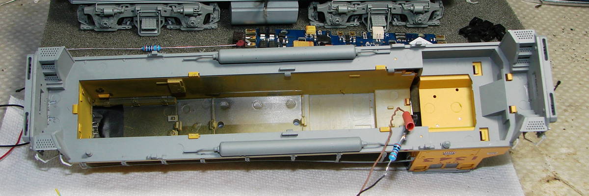
| This view shows the shell and you can see the molded retaining clips (gray) near the center. The shell is a tight fit. The OEM wiring ends at a plug at the motherboard and can be disconnected if desired. Note, the wiring with the resistor is not original, it is a modification I was working on; please ignore. | |
 |
|
 |
|
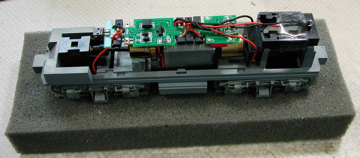
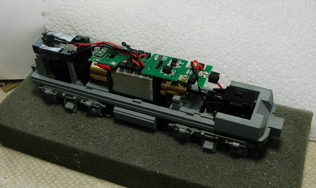
Here are two pictures of the model with the shell removed. In the picture above, the 21 pin decoder connector is shown to the right of the motor pointing down. As you can see, the flywheel is notched to clear the decoder. The speaker box is shown supporting the headlight LED. |
|
| This is a top view of the motherboard with the 8 pin shorting plug removed. | 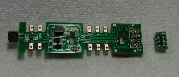 |
| Pictured is the bottom view of the motherboard showing the 21 pin connector. | 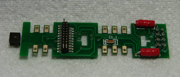 |
| This is the speaker support frome (black) which I have modified to hold my 3D printed 11 x 15 micro speaker box (gray). I use acrylic caulk to assemble the parts. | 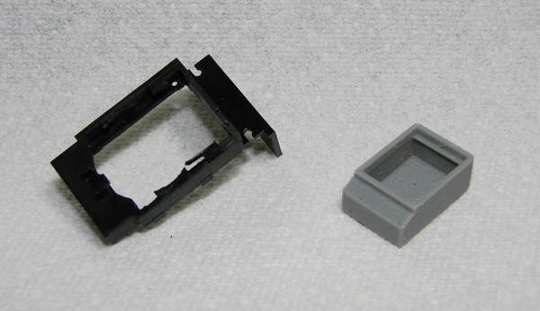 |
| I am sorry but I don't have any pictures of the 21 pin decoder installed. It should be a simple matter to install the decoder, add the speaker and connect the wires to the terminals on the motherboard. | |