Add A Soundtraxx Decoder To A Gem Brass 2-4-4-2 (1970 ver)
Jim Exler Nampa, ID March 12, 2024
The front chassis is held on by the pivot screw on the rear chassis. Mine had a washer to watch for. The exhaust tube can be removed by moving it in the slot until the keeper clears. Pay attention to each screw as there are many different patterns used.
The rear chassis is held on by 2 screws at the rear of the cab and one above the steam chests under the boiler.
The tender body is held on by 4 screws in the corners accessible by removing the trucks.
 |
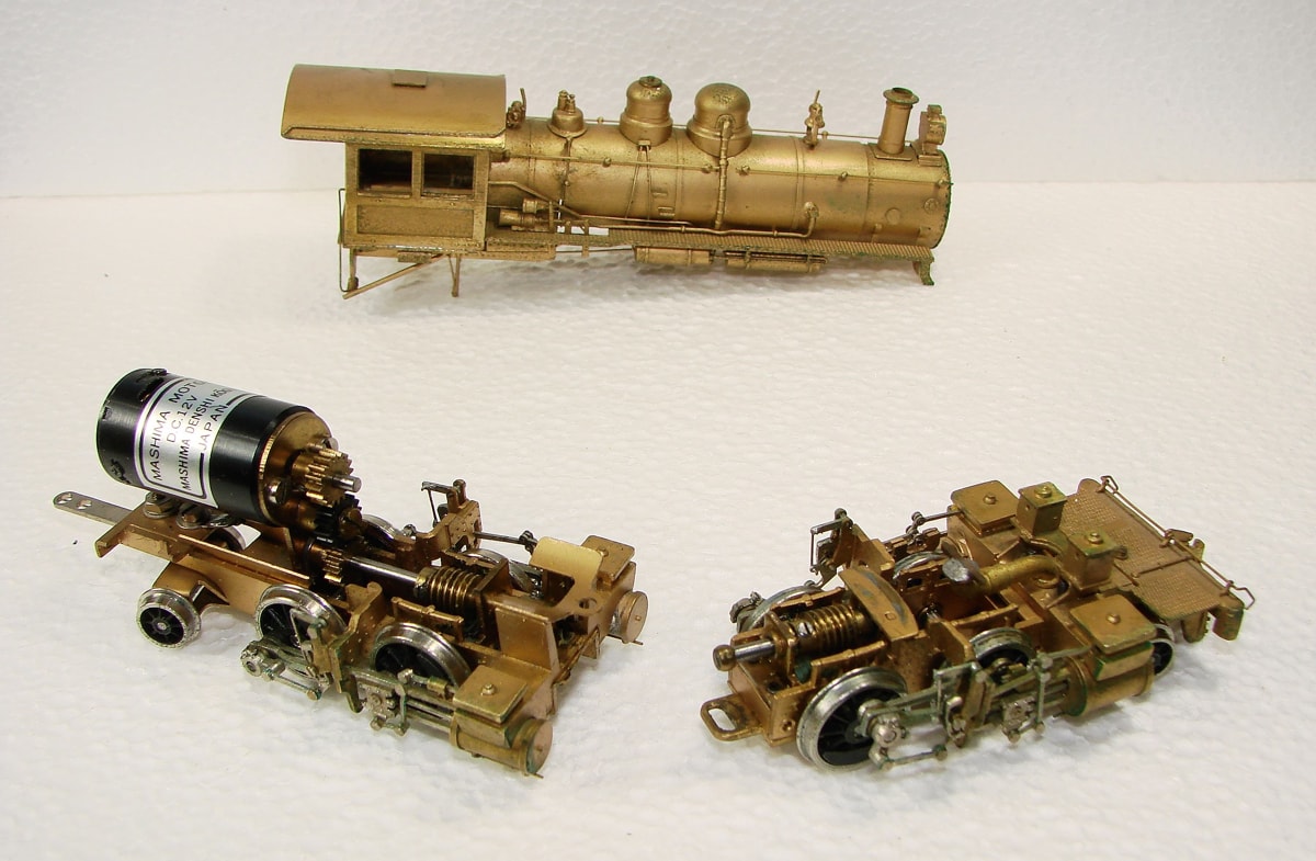 |
Here are 2 views of the basic assemblies. To add LED SMD chips to the light housings, I drilled 2 holes at a steep angle down from inside the lamp housing into the boiler and tender body. The front drilling stayed within the casting but the rear drilling is exposed below the casting going into the tender body. Once installed and painted, it will just look like conduit and should not be objectionable. |
 |
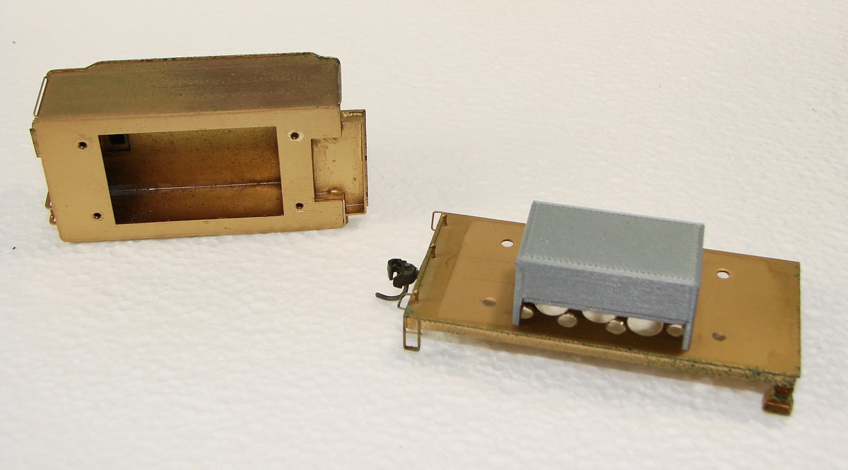 |
These show the tender components and my 3D printed speaker box. A diagram is below. |
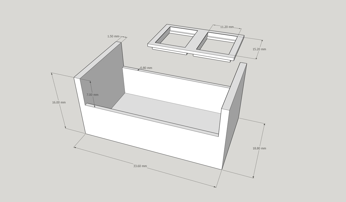 |
My 3D printed speaker box. It uses 2 15x11 "sugar cube" speakers wired in series for extra bass. I use acrylic caulk to assemble the box and mount the speakers. Ask if you want the model file. Click to download the 3D print stl files for this speaker box and dual mount cover. |
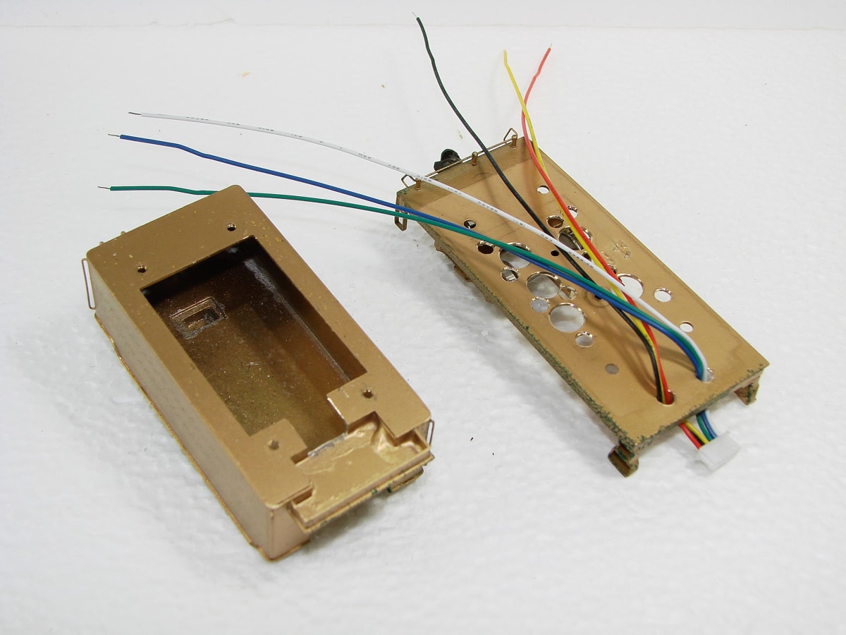 |
Here, the tender body has had a notch cut in it to allow the wires from the locomotive to enter. I used a 6 wire connector between the units. Originally, the tender floor had a 1oz lead weight fastened at the center. To replace that weight, I used 4 pieces 1/4oz and mounted them with double sided foam tape in the 4 corners of the body. The weights were cut from a piece of flat peel and stick automobile wheel weights I scrounged from a tire shop. They always remove the existing weights and rebalance with new ones. |
 |
| A loop of copper wire has been added to funnel the wires from the holes into the notch in the tender body. |
 |
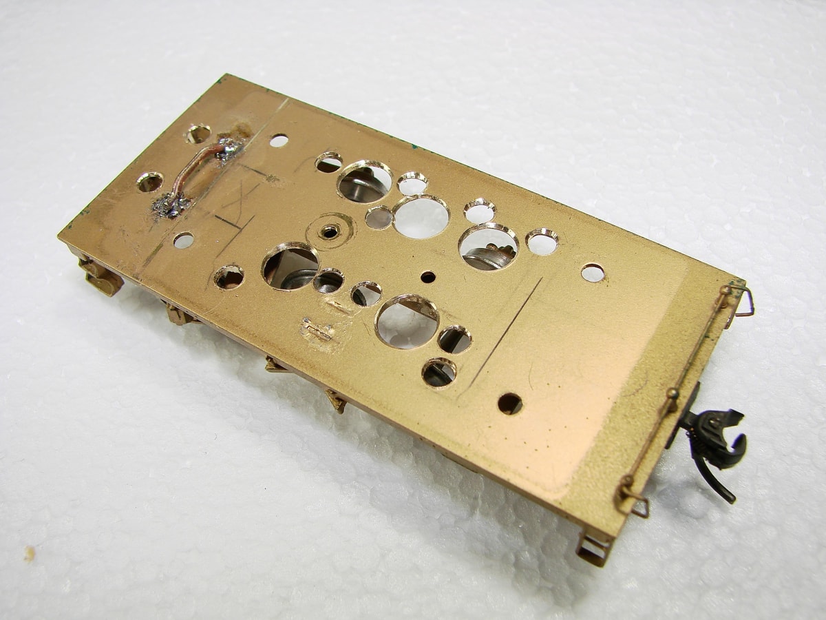
| 2 pieces of 0.125" square tube are added as conduits to keep the wiring from the connector from fouling the trailing truck. They are shown just to the left of the drawbar. I used super glue rather than solder so as not to disturb the joints on the frame. |
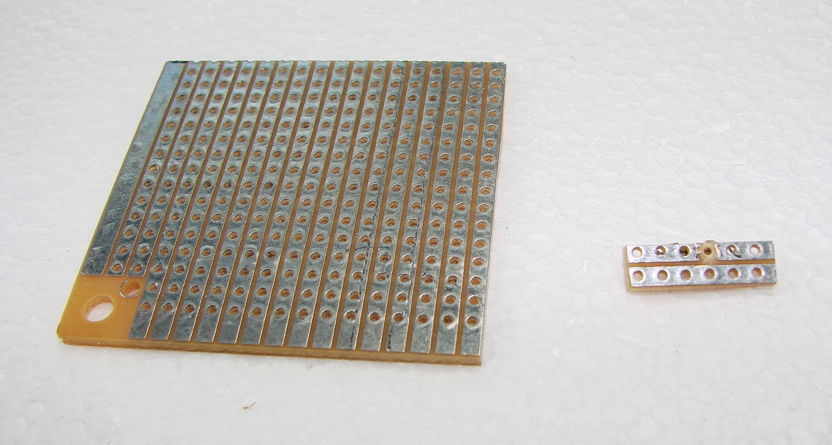 |
| To accommodate the LED resistors, I cut pieces of strip board and cut one trace under the resistor location. |
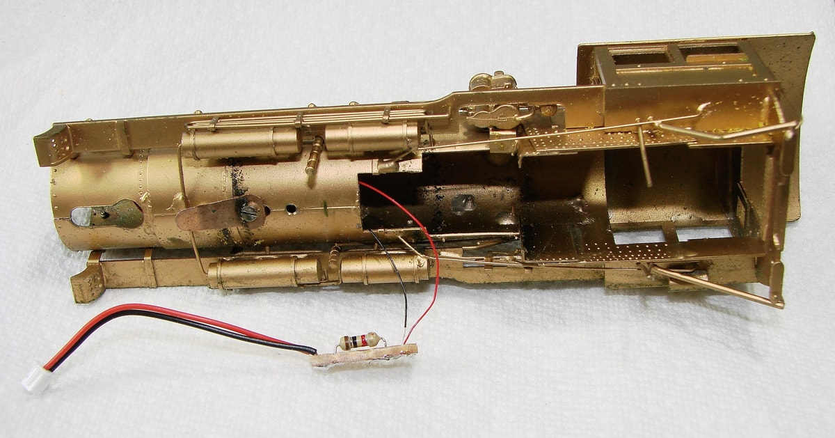 |
| With the resistor in place, the wires from the LED and the feed connector are soldered and then insulated with a piece of shrink tubing. I pushed the assembly into a cavity next to the boiler weight in the forward part of the boiler. |
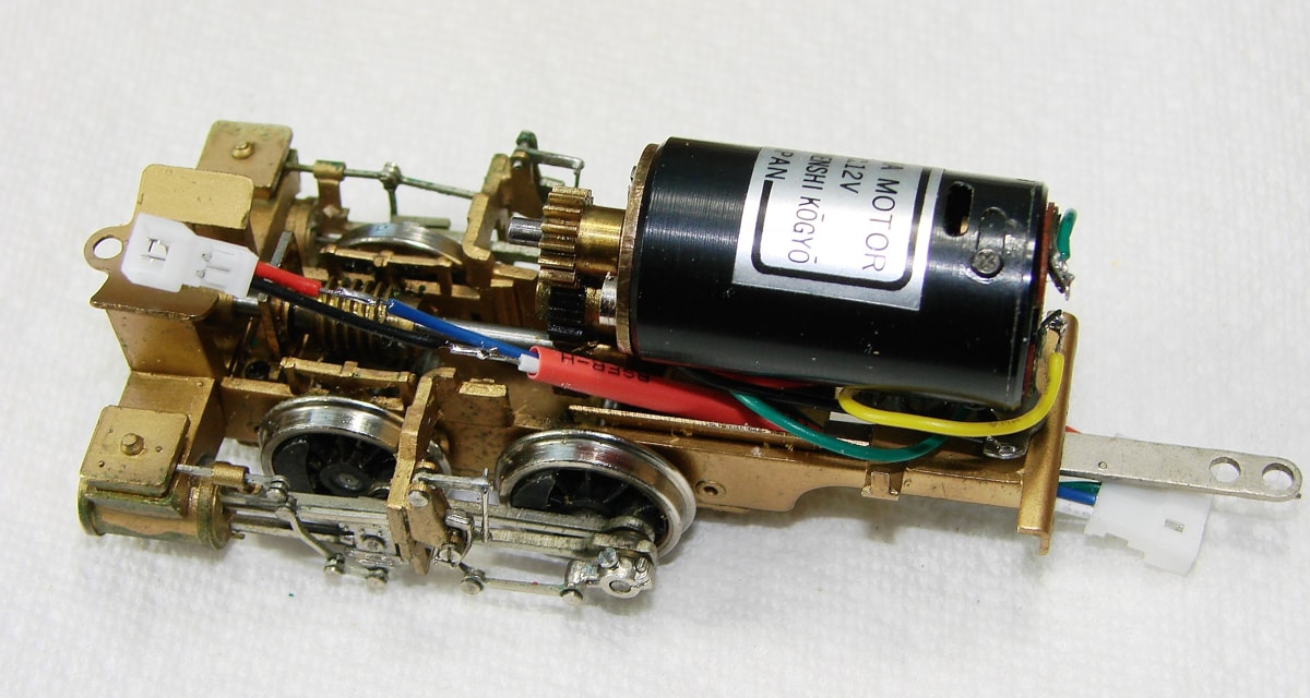 |
The wiring has been connected to the motor and the light connector. The shrink sleeve needs to be placed over the splices. The red right rail feed was connect to a lug on the chassis and the black left rail feed was connected to the insulated drawbar. If I need to add a left rail pickup to the loco, I can connect it at the drawbar lug. So far, it does not seem to warrant the extra pickup. |
| The decoder I chose is a Soundtraxx TSU-1100 Steam-2 Sound Decoder ~ 884006 |
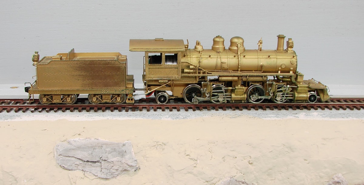 |
| The loco after the install waiting for a slot in the paint shop. |
| Click to download a short movie of the loco in motion |